Case study collection
MatCalc Engineering GmbH is involved in various projects for our customers in different private sectors such as alloy producers, automotive industries, energy suppliers, medical industries, nuclear industries and semiproduct producers. However, most of our works for commercial customers are confidential. Below are few typical generic examples of our works applied for a variety of different material classes. Each solution is applicable to other materials too.
Our material characterization capabilities show what the real microstructure of the material is and our modeling tools help to understand why a given microstructure appears and how to influence its further evolution.
Regardless of the type of your project; a concept formulation and evaluation, realization or optimization and / or through process modeling the benefits of our simulation works is obvious. We help plant engineers to analyze and solve practical problems much easier, optimizing each process step in view of the consequence on final product and increases industrial process variability and at the same time material quality. Our results have positive impact on waste management by reducing defects and decreases significantly time and cost for development.
Casting
Solidification of the alloy is usually the first stage in the metallurgical process chain. The properties of the solid material are created here and will be the subject of the subsequent process stages. The extent of the compositional inhomogeneity and the presence of the precipitates formed directly from the liquid phase will influence the further microstructure evolution.
With the available thermodynamic description, the evaluation of segregation and primary precipitation during casting can be performed based on the Scheil-Gulliver calculation. Scheil-Gulliver analysis utilizes the thermodynamic data to the simulation of the liquid alloy transformation toward the solid phases. It gives information about the number, the amount and the chemical composition of the created phases over the relevant temperature range. With this insight, various system compositions might be tested to find the optimal properties of the solidified material.
Typical application examples:
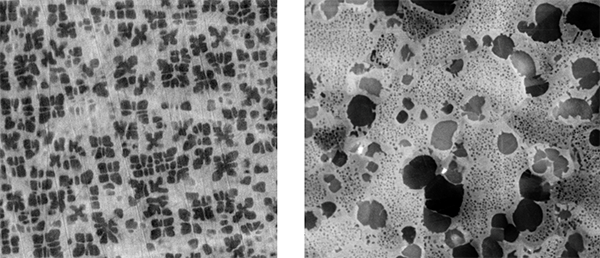
Figure: Applying Scheil simulation with our thermodynamic database ME-Al (left), we can identify the primary precipitates in as-cast Al-alloy (SEM-image of dendritic microstructure of AA319, right).
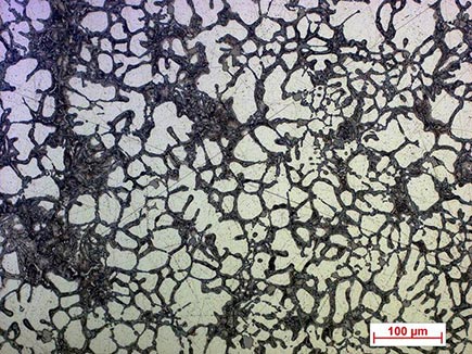
Microsegregation in microalloyed steel is studied in the Scheil-Gulliver module of MatCalc. It is used to predict primary precipitates during the continuous casting process. Primary precipitates in microalloyed steel, which are marked by circles, are visible in Figure 1.
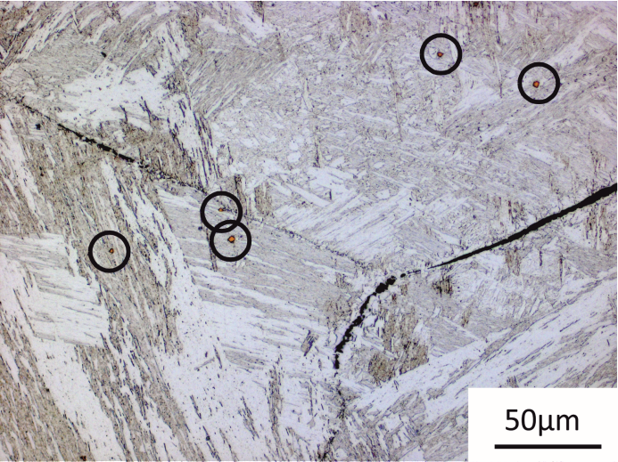
Figure1: Microstructure – primary precititates
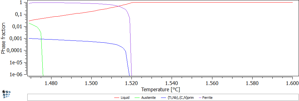
In the calculation, back diffusion of carbon and nitrogen as well as the peritectic reaction is considered. The results can be seen in Figure 2. Primary (Ti,Nb),(C,N) precipitates with a phase fraction of 0.1% are predicted.
Figure2: Scheil Gulliver simulation of solidification
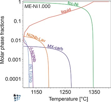
Figure 1: ME-Ni prediction of primary phases formed during continuous casting of Ni-base superalloy IN718. Laves-phase (Ni,Cr,Fe)2(Nb,Mo) forms as primary particle due to segregation. In equilibrium, this phase is stable in a narrow temperature range around 1000°C in IN718.


On the left, a scanning electron microscope picture of the as-cast structure of AA7050 is shown with numerous primary precipitates. On the right, the results of the Scheil-Gulliver calculation relevant for this system are displayed, which show good agreement with the experimental measurements and the predictive power of the calculations.
Heat treatment
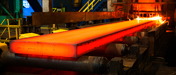
With our thermodynamic and diffusion databases the effects of the heat treatment operations on the alloy structure can be studied. We offer solutions for various Heat-treatments such as homogenization, solution treatments, ageing, annealing,...
Typical application examples:
Transverse cracking on the surface of as-cast products is a long-standing problem in continuous casting of steel. Surface cracks occur mainly in the bending and straightening operations in a curved type continuous caster in a temperature range of 600°C to 1200°C. The reasons for this are either strain concentrations at film-like ferrite along austenite grain boundaries and/or precipitation of second phase particles. A high density of fine precipitates leads to (local) precipitation hardening with intensive stress concentrations, thus triggering the nucleation of wedge-type cavities as well as favouring interconnection of cavities surrounding the precipitates (Figure 1). This makes up the main mechanism of reduced ductility in the austenitic high-temperature region.
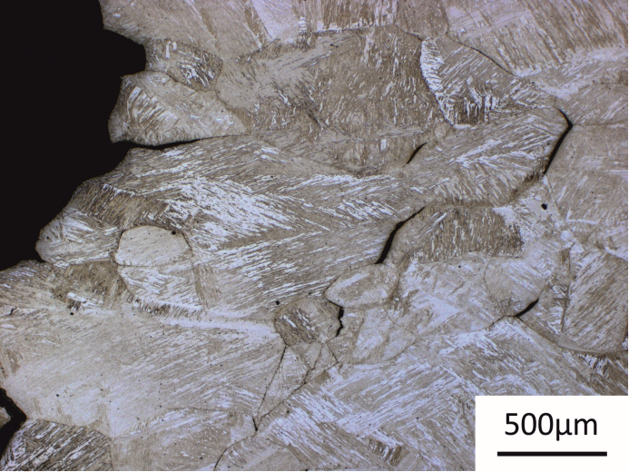
Figure1: Wedge-type cavities in microalloyed steel.
Experimentally, the probability that steel might suffer from transverse cracking in the course of the straightening operation during continuous casting is commonly assessed by hot tensile tests in a thermo-mechanical simulator (e.g. Gleeble). Thermokinetic simulations with MatCalc can predict the precipitation state, which corresponds to the particular heat treatment state. With this information, it is possible to estimate the susceptibility of transverse cracking. In the simulation, the complete thermo-mechanical history of the material, including the strain rate of deformation is considered.
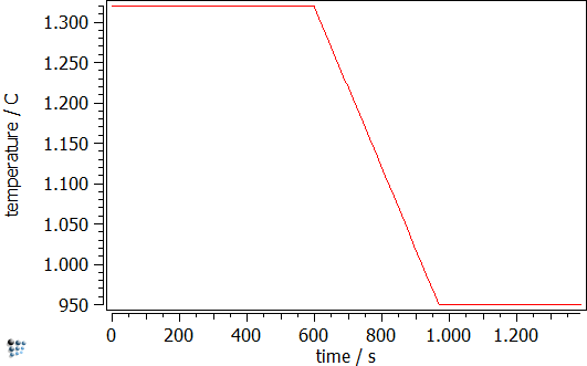
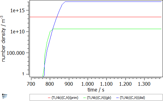
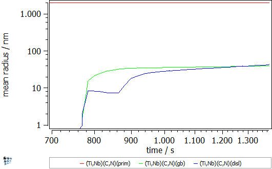
The simulation starts with the cooling segment in the continuous casting process. Afterwards follows the heat treatment, which is performed on the Gleeble. The specimens are solution treated at 1320°C and, then, cooled down to test temperature, where tensile deformation is applied. The simulated strain rate is 1∙10-3s-1 and the simulation is stopped once the specimens have been fractured in the experiment. Figure 2 displays the calculated evolution of the mean particle radii and the number densities during the Gleeble heat treatment.
Figure2: Calculated evolution of the mean particle radius and the number density of (Ti,Nb),(C,N) precipitates.
On some occasions that the material is not homogeneous or by typical examples of the cast materials with microsegregation, the existing composition gradients in the system can be disappeared with various time-temperature process cycle(s). Depending on the target, it might bring advantages or disadvantages for the material. It is possible to predict in advance the outcome and consequence of the process cycle(s).
With available data for chemical potentials and mobilities of the system components, the diffusion processes leading to the microstructure homogenization can be simulated. The concentration profiles for various annealing times at various temperatures can be estimated. Moreover, it is possible to perform the precipitates kinetics simulation in this changing environment to realize the consequential microstructural evolution.
Homogenization of Ni-based alloy PWA 1480: We use our thermodynamic and diffusion databases in “cell simulations” to predict requirements of homogenization heat treatments of cast alloys. The results of these “cell simulations” with ME-Ni database represent, for instance, the development of temperature-dependent element diffusion profiles between dendrite core and interdendritic area of a cast single-crystal Ni-base superalloy as a function of annealing time.
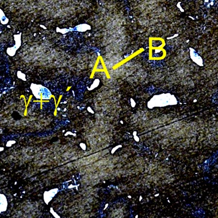
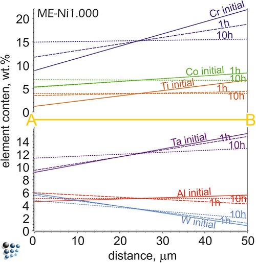
The metallographical picture of the PWA 1480 alloy structure with etched dendrite structure (bright cross-shapes) cut along (001) of the fcc matrix structure. A one-dimensional diffusion profile along the A-B cross-section simulated with MatCalc for the sample homogenized at 1300°C for various time periods are shown below. Sample is homogenized after 10 hours.
Precipitation evolution
Precipitates appear frequently in processed alloys. On some occasions, these are introduced intentionally to improve material strength. In other cases, the appearance of precipitates might be disturbing, e.g. intermetallics in specific welded parts. Undoubtedly, an insight into the precipitation evolution during the process is of a great value.
With over 20 years of experience on this specific topic, our models have proved their realistic functionality of prediction in different applications. Our developed solutions and the approach for the prediction of the precipitate/matrix interfacial energy and the size evolution of the precipitates are broadly recognized in the scientific community. We are able to track the precipitates sizes, numbers and compositions of them during the whole thermomechanical process chain.
Typical application examples:
We can predict nucleation start temperatures during continuous cooling from solid solution based on thermodynamic modeling, e.g. evaluation of discontinuous heat flow due to precipitation of metastable precipitates in Al-alloy AA6016 during continuous aging, simulated with ME-Al database.
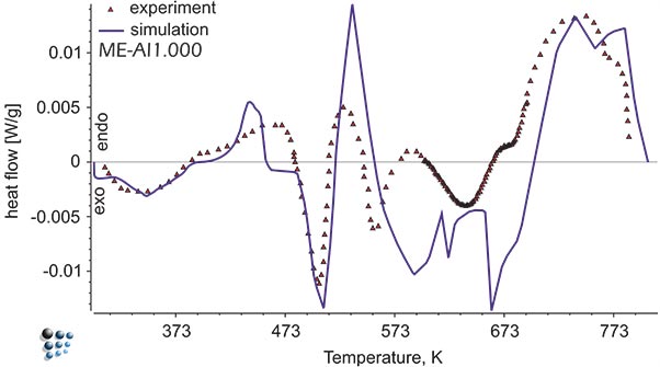
Figure1: Simulated heat flow curve versus experimental data in Al-alloy during continuous aging. The exothermal peaks represent precipitation of metastable intermetallic phases.
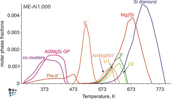
Figure2: Simulated fractions of precipitates in Al-alloy during continuous aging.
In this example, the growth and coarsening behavior of MnS precipitates for three electrical steel grades during hot deformation is investigated. The specimens were solution treated at 1300°C for 30min and afterwards immediately cooled to test temperature and a constant stress was applied. Precipitation of MnS occurs simultaneously on grain boundaries and dislocations.
Figure 1 and 2 show the calculated radius versus time curves of MnS precipitation in three different alloys at temperatures of 800, 900 and 1000°C. Figure 1 summarizes simulation results for MnS precipitates located at grain boundaries, whereas precipitates at dislocations are shown in Figure 2.
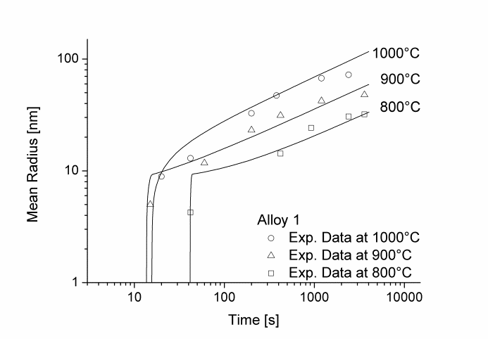
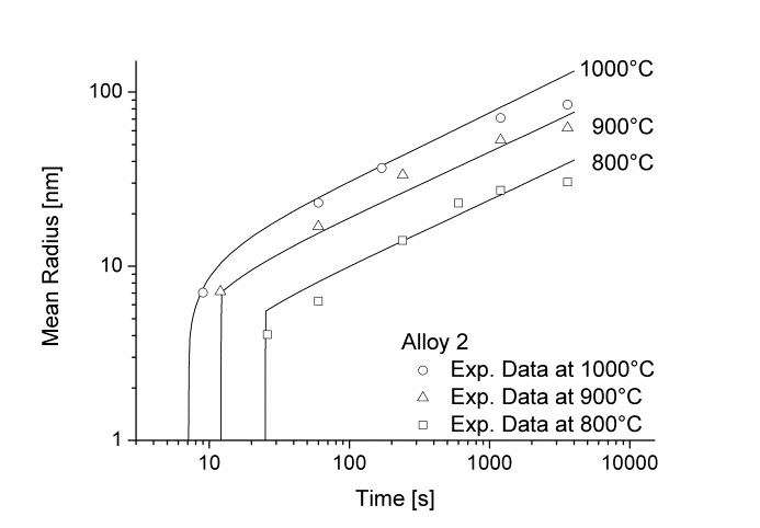
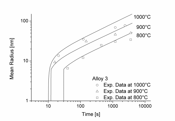
Figure1: Calculated and experimental mean radii of MnS located at grain boundaries for various temperatures
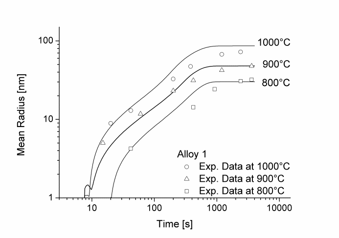
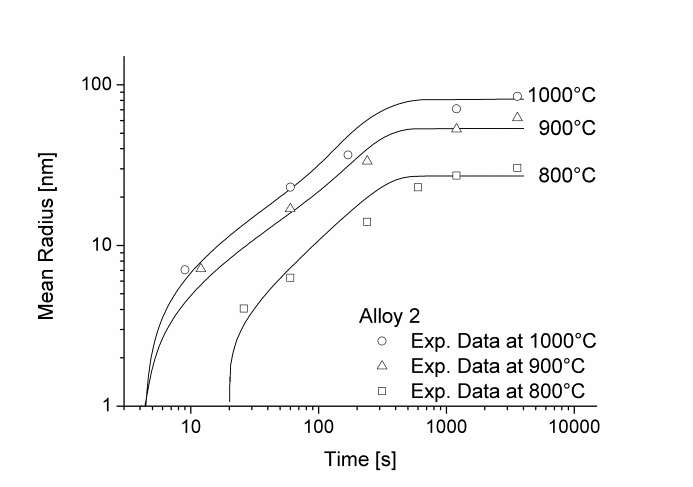
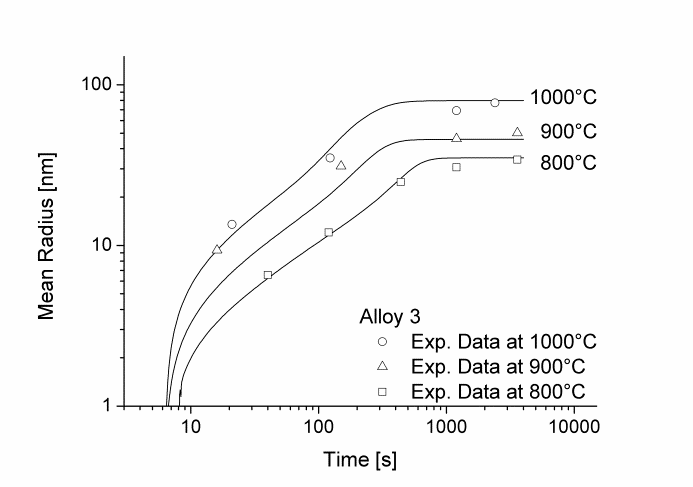
Figure2: Calculated and experimental mean radii of MnS located at dislocations for various temperatures
In this example, the yield strength simulation in binary Fe-Cu is shown. The strength of a material should be calibrated in a “simple” system and, then, the parameters can be transferred to complex alloys. The precipitation of Cu in Fe-Cu is based on the data of Goodman et al. (1973). It starts off with the nucleation of coherent bcc-Cu and evolves with the transformation to the semi-coherent 9R structure and the incoherent fcc-Cu. A direct-particle transformation is used for the evolution of Cu-precipitates. Figure 1 displays the calculated evolution of the mean particle radii, the number densities and the phase fractions of the different stages of Cu precipitates.
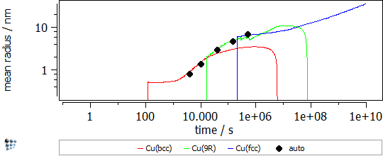
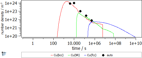
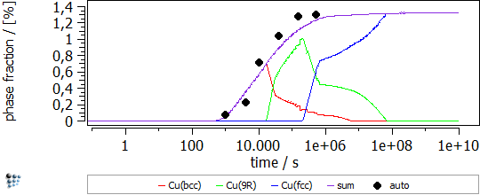
Figure1: Calculated evolution of the mean particle radii, the number densities and the phase fractions of Cu precipitates
In Figure 2 the particle strengthening contribution to the yield strength is visible (red line). The other contributions, like work hardening, intrinsic lattice strength, solid solution strengthening, grain size strengthening and subgrain size strengthening, are considered for the green line.
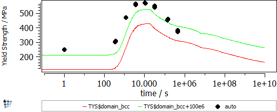
Figure2: Yield strength in binary Fe-Cu
Our characterizations of microstructures, precipitate distributions and types of precipitates by metallographic techniques and transmission electron microscopy support our simulation results on precipitate sizes and distributions, such as bimodal to multimodal particle distribution in some solution-treated single-crystal Ni-base alloys, evolving during continuous cooling.

Figure1: Energy filtered transmission electron microscopy (EFTEM) picture of the multimodal gamma prime precipitate distribution.
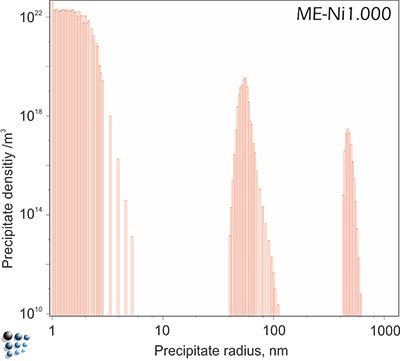
Figure2: Simulated multi-modal distribution of gamma´ precipitates during continuous cooling with 0.1°C/s in technological Ni-base superalloy Udimet720.
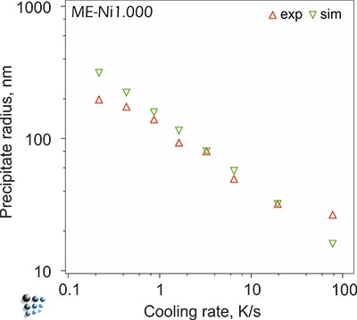
Figure3: Simulated size of secondary precipitates in Udimet720 compared with experiments.
Microstructural modeling
Microstructure features like precipitates distributions, dislocation density, grain/subgrain sizes, as well as vacancy concentration are decisive for the material properties. Capability of microstructure evolution modeling gives us a great advantage in understanding, planning and optimizing of the process parameters.
Instead of a bunch of independent models, we succeed to develop a coupled framework considering the mutual interactions of the microstructure elements and as a consequence a solution for the microstructure evolution simulations.
With our available modeling technique, the microstructure parameters of different materials can be calculated during and/or after various thermomechanical operations, such as rolling, extrusion and forging.
Typical application examples:
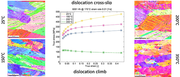
We simulate the microstructure-precipitation inter-relations in alloys, using physical and semi-empiric models for dislocation substructure development, grain growth and recrystallization.
The simple example in the figure below shows the importance of excess dislocations formed during deformation for the kinetic simulation results: An increase of dislocation density of two orders of magnitude in tortion-tested microalloyed austenite relative to unstrained material is expected and leads to a perfect reproduction of the precipitation evolution during isothermal heat treatment.
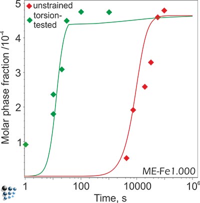
Phase fraction evolution of NbC precipitate in microallyed steels with and without deformation. The dislocations introduced during the deformation accelarate the precipitation kinetics, both by increasing the number of nucleation sites (in this system, NbC nucleates mainly on dislocations) and by diffusion enhancement.
Al-Mg-Si alloys are widely used as age-hardenable alloys. The main hardening contribution comes from the precipitates formed in the material. As the diffusion processes depend on the vacancy amount present in the system, it is important to have some insight into the vacancy concentration in order to simulate the precipitation kinetics in these systems. In case of aluminium alloys, the high cooling rates result in the considerable amount of the excess (frozen-in) vacancies so that taking the equilibrium concentration of vacancies for the kinetic simulation may lead to serious errors in the predictions of the precipitation state of the material.
In this example, the effect of quenching process on the natural ageing process in Al-Mg-Si alloy is discussed. The alloy is solution annealed and, afterwards, quenched in two ways. The first way is a standard water-quench to room temperature (treatment P1). The other way is to quench in a low-melting alloy at 160°C, hold it at this temperature for two minutes and, subsequently, quench in water to room temperature (treatment P2). Figure 1 shows schematically the treatment features.
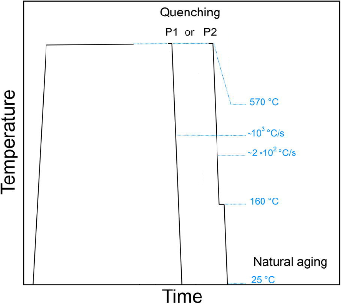
Figure1: Heat treatments investigated in this example. Treatment P1 ends with the water-quenching to room temperature. Treatment P2 includes an isothermal hold for two minutes at 160°C before reaching the room temperature.
Differences in the precipitation kinetics were observed for these treatments. The resistivity measurements (Fig. 2) show a clear change of the sample state treated with P1, while no such behavior is observed for the sample treated with P2. The atom probe tomography (APT) analysis shows also differences in the amount of clusters found (Fig. 3). The cluster distribution of P2 sample is identical with the random distribution (except of a single precipitate which seems to be found by chance), while the sample P1 shows indicates clustering.
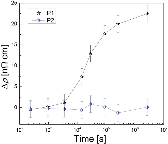
Figure2: Results of the resistivity measurement of the samples stored at room temperature after various heat treatments. Resistivity increase after treatment P1 was observed. For the sample after treatment P2, the resistivity retained its value.
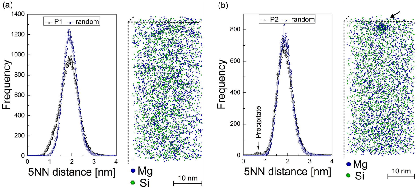
Figure3: Results of the Atom Probe Tomography measurement of the samples stored at room temperature after various heat treatments. The cluster analysis in the sample after treatment P1 (a) shows a remarkable deviation from the random solution model. The results of this analysis in the sample after treatment P2 (b) confirm the random distribution of the solute atoms with an exception of a single heterogeneous precipitate was found.
The way in which these heat treatments result in the different behavior is revealed when the evolution of the vacancy concentration is analyzed. On one hand, the equilibrium vacancy concentration at room temperature is the same for both of the samples and it does not provide any explanation for the different outcomes. Nevertheless, the FSAK model which is implemented in MatCalc, calculates the actual vacancy concentration and it predictions (shown on Fig. 4) allow some understanding of the processes occurring in these samples. For treatment P1, the straight quenching results in the high concentration of the excess vacancies. These had not enough time during cooling to reach the sinks at which the vacancy annihilation occurs. Hence, these vacancies are available for the diffusion of the solute atoms of Mg and Si which tend to form clusters at room temperature. In case of treatment P2, the isothermal holding at 160°C is in the region when the vacancy mobility towards sinks is still considerable and the amount of the frozen-in ones is over two orders of magnitude lower than at the end of treatment P1. In result, the diffusion of solute atoms at room temperature is inhibited and the cluster formation is prevented during the measured timescale.
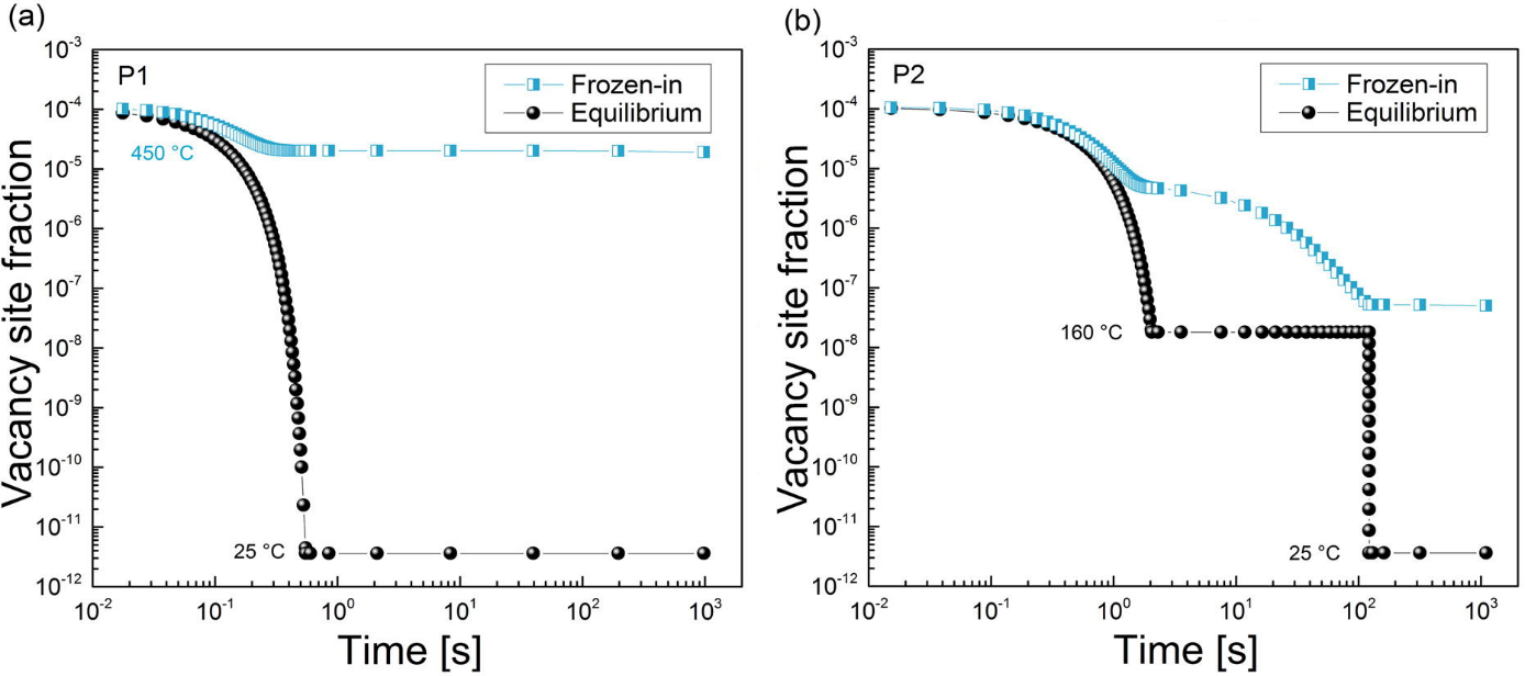
Figure4: Evolution of the equilibrium and actual (frozen-in) vacancy concentration in the samples after treatment P1 (a) and P2 (b). While the predicted equilibrium concentration is the same in both samples, the concentration of the current ones is over two orders of magnitude larger after treatment P2 than after treatment P1.

A simulation of the recrystallization progress in V-microalloyed steel for two strain values of 0.2 (left) and 0.35 (right) in compare with experimental findings (points). Recrystallization retardation by small precipitates of vanadium nitride is predicted for lower temperatures.
Mechanical properties
Mechanical properties of a material are controlled by the microstructure of the material. Microstructural evolution of a material during technological processes can be calculated by our software simulation capabilities. Therefore, it is possible to determine the mechanical properties during the process and to estimate the impact of different process modifications on the final material properties.
Our yield strength model takes in to account the contributions of work hardening, grain and subgrain sizes, solid solution and precipitation strengthening effects based on the simulated microstructure evolution. Furthermore, the flow stress can be calculated at various temperature and Strain rates.
We provide analysis of composition variation effects on the mechanical properties, estimations of heat treatment parameters to achieve maximal strength but avoid overageing, predictions of flow curves and…

Typical application examples:
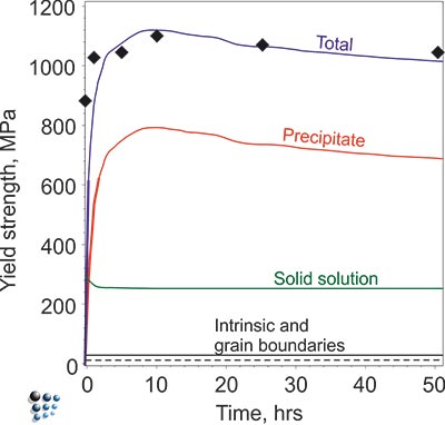
Figure1: Evolution of total yield strength of a solution-treated technological Ni-base superalloy due to γ´ precipitation during isothermal aging. Lines are simulated, symbols are from experiment.
We evaluate matrix compositions in good agreement with experimental data. Combined with collected strengthening coefficients, our quantitative simulation results enable the prediction of solid solution strengthening.
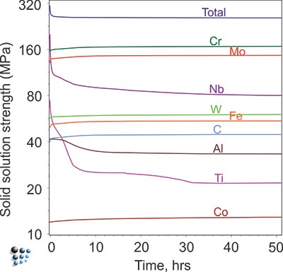
Figure2: Prediction of solid solution strengthening in aged wrought Ni-base superalloy IN718.
In this example, the yield strength simulation in binary Fe-Cu is shown. The strength of a material should be calibrated in a “simple” system and, then, the parameters can be transferred to complex alloys. The precipitation of Cu in Fe-Cu is based on the data of Goodman et al. (1973). It starts off with the nucleation of coherent bcc-Cu and evolves with the transformation to the semi-coherent 9R structure and the incoherent fcc-Cu. A direct-particle transformation is used for the evolution of Cu-precipitates. Figure 1 displays the calculated evolution of the mean particle radii, the number densities and the phase fractions of the different stages of Cu precipitates.


Figure1: Calculated evolution of the mean particle radii, the number densities and the phase fractions of Cu precipitates
In Figure 2 the particle strengthening contribution to the yield strength is visible (red line). The other contributions, like work hardening, intrinsic lattice strength, solid solution strengthening, grain size strengthening and subgrain size strengthening, are considered for the green line.

Figure2: Yield strength in binary Fe-Cu


Weld bead configuration First droplet exposed temperature profile


Evolution of precipitate phases in the first droplet Yield strength of first droplet during welding
Simulation of the yield strength of the first droplet of the filler material (Cr-Mo microalloyed steel) exposed to heat treatment effect of the other covering droplets.

Scheme of the heat affected zone thermal history (Tmax-value approaches Tend with the increasing distance from the fusion zone).

Yield strength within the heat affected zone as a function of the distance from the fusion zone. The contribution of the solid solution and precipitation hardening effects are visualized.
Welding
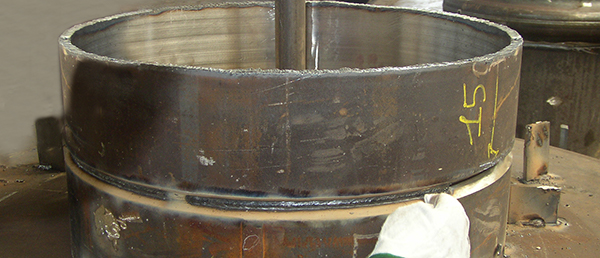
Welding is a popular method to join materials. Local application of a heat source on a material for a short period of time can have a tremendous effect on the microstructure of that material. If the heat source is strong enough or a filler material is used, there exist melting, solidification and heat treatment at the same time and the process can be much more complex. Our physically based simulations can shed light on the complexity of the welding process microstructural evolution.
Thermodynamic and precipitation kinetics models allow us to predict the formation and growth of intermetallic phases. Furthermore, the microstructure evolution models give information about the grain size development. These results combined with the diffusion modeling allow simulating the various regions of the material with no uniform composition. Finally, the mechanical properties of the selected product part can be estimated.
We provide welding simulations of dissimilar material parts, analysis of the base and filler material properties and predictions of the weld microstructure evolution in specific service conditions.
Typical application examples:


Weld bead configuration First droplet exposed temperature profile


Evolution of precipitate phases in the first droplet Yield strength of first droplet during welding
Simulation of the yield strength of the first droplet of the filler material (Cr-Mo microalloyed steel) exposed to heat treatment effect of the other covering droplets.


Scheme of the heat affected zone thermal history (Tmax-value approaches Tend with the increasing distance from the fusion zone).

Yield strength within the heat affected zone as a function of the distance from the fusion zone. The contribution of the solid solution and precipitation hardening effects are visualized.
Through-process modeling
Rising number of international competitors enforce producing companies to optimize their production process routes and offer high-quality products to be able to stay competitive in the global market. The number of influencing factors and parameters in the whole process-chain is tremendous. Any experimental investigation of the resulting material characteristics for optimization purpose or property prediction is highly time-consuming and cost-intensive with limited applicability.
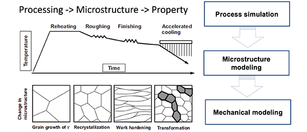
For through process modeling, the major issue is to track the evolution of microstructure throughout the manufacturing process chain from casting after solidification to the final product and the challenge is to integrate correctly different sub-models by properly defining their interactions. An overview of the material state resulting from each single operation is a key for process optimization and the creation of a cost-effective technological production line.
We provide simulation package based on fully integrated models incorporated in the software MatCalc that be capable of a complete trough-process modeling for each production route. Beginning with casting and ending with the simulation of the last thermomechanical operation of the final product. An intelligent optimization can only be reached when the combined influence of all the processing parameters during fabrication is known and is taken into account. After that various process- and material-related scenarios can be tested with an analysis of their impact on the material microstructure and properties.
Typical application example:
Each processing step changes the microstructure and, therefore, affects the properties of the material. The final properties of aluminum plate depend not only on the chemical composition of the material but also on the microstructural evolution throughout the processing route.


A scheme of the process chain for the production of aluminum alloy sheets and their relevant material characterization steps.

Last production step (ageing): A typical Al-Mg-Si alloy strengthening as a function of the precipitation kinetics during the last ageing treatment. In this simplified version just the evolution of b” phase during ageing has been shown.
Characterization
MatCalc Engineering GmbH has the technology, the expertise and the background to perform different experimental methods to provide answers to our customer questions. Generally the techniques used for a given problem are selected based on the information needed. A range of characterization and testing services with interpretation of the results can be found here.
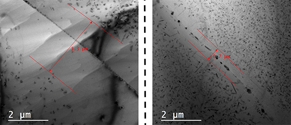
Rod shaped metastable precipitates (see long lines in Fig.) in an AA6xxx were characterized by means of their distribution, size, orientation and shape factor. Thickness measurements of the observed volume allow the estimation of local particle number densities and further their volume fractions. On the right edge of Fig., a grain boundary pinned by dispersoids is visible. The size and the chemical composition (EDX) of these dispersoids as well as the size of the precipitation free zone (PFZ) can be measured. The blurred dark lines and regions are bending contours and thickness fringes of the Al-matrix and are the consequence of the diffraction contrast. All this knowledge gives a qualitative and quantitative insight into the material and allows a better setup of simulations and the optimization of ageing processes.
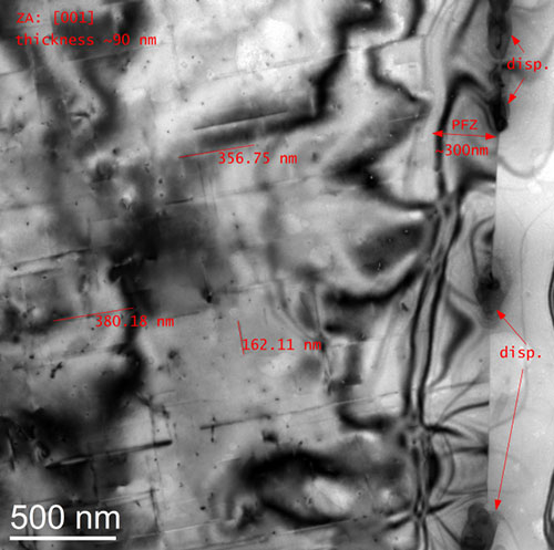
TEM bright field image of a 6xxx Al-alloy.
Figure 1 shows a Transmission Electron Microscopy (TEM) image of carbides (dark contrast) in quenched and tempered steel. The elongated carbides occur on lath-boundaries and are identified as cementite by the use of electron diffraction. The estimated size of martensite laths is related to the quenching process.
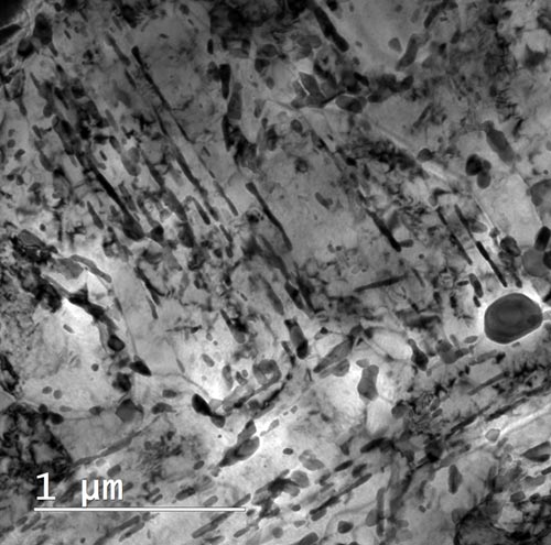
Figure1: TEM bright field image of a thin foil.
A Scanning TEM image shows contrast related to different atom masses of the same region (see Fig. 2). The chemical composition of the particle marked as “EDS spot 1” is a Cr-rich carbide. Its EDX spectrum is shown in Fig. 3.
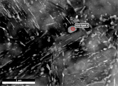
Figure2: STEM HAADF image (mass contrast) of the same region as Fig, 2.
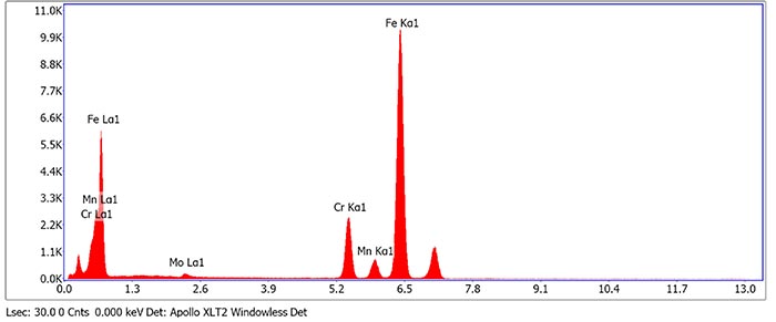
Figure3: EDX spectrum of the particle marked as "EDS Spot 1" in Fig. 2. In addition to Cr and Fe the carbide also dissolves Mn and Mo.
A complex heat treatment leads to a multimodal distribution of TiN precipitates in microalloyed steel. The figure below shows a Scanning Transmission Electron Microscopy (STEM) image with mass contrast (HAADF; the heavier, the brighter) of these particles. In this particular case the precipitates are extracted from the Fe matrix onto a thin carbon film (replica). Using this technique we are able to analyze particles down to several nanometers in size without disturbing contribution of the Fe matrix. Fig. shows three size populations of TiN precipitates. The chemical compositions of the nanoparticles were estimated using Energy Dispersive X-Ray Spectroscopy (EDX) and Electron Energy Loss Spectroscopy (EELS). The measurement of the sizes, chemical compositions and frequency of each population allows a better understanding of nitride precipitation and optimizing of the heat treatment.
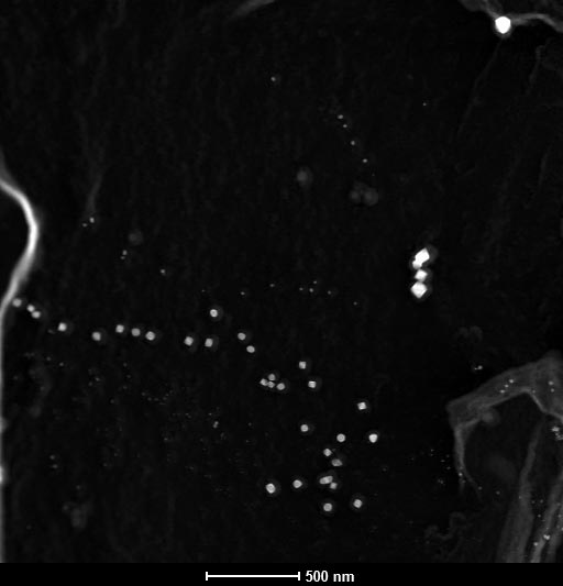
STEM HAADF image of TiN precipitates in microalloyed steel (carbon extraction replica).
Single crystal superalloy alloy: γ’ precipitates
Fig. 1 shows a TEM bright field overview of a single crystal creep resistant superalloy with coherent cuboid γ’-precipitates. The size, shape and aspect ratio of these secondary precipitates are characterized.
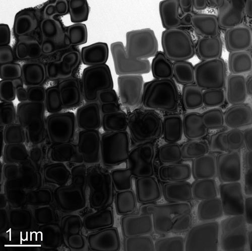
Figure1: TEM bright field image of γ’ precipitates in a Ni-base single crystal alloy.
The use of electron diffraction and dark field imaging reveals tertiary precipitates in the channels between the secondary cuboids (see Fig. 2).
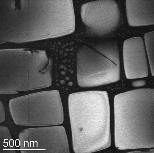
Figure2: TEM dark field image of Ni-base single crystal alloy with nano-sized tertiary γ’ particles in channels between the secondary cuboids.
Polycrystalline superalloy: γ’’ precipitates
Fig. 3 shows three grains (different contrast values) with precipitates in a polycrystalline superalloy.
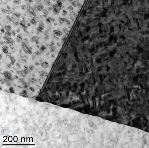
Figure3: TEM bright filed image of polycrystalline Ni-base alloy with platelet shaped γ'' precipitates in three neighboring grains.
Using electron diffraction (Fig. 4) the precipitates are identified as γ’’. The strong diffraction spots belong to the Ni matrix, the weaker spots result from the γ’’ precipitates.
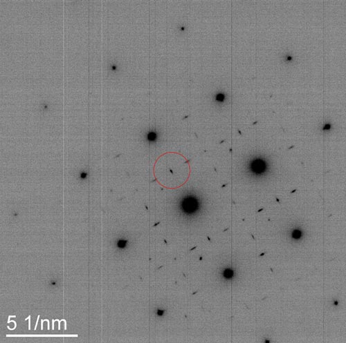
Figure4: Diffraction pattern of the dark grain in Fig. 3. Weak diffractions spots between the strong ones (Ni matrix) are related to the γ'' precipitates.
Fig. 5 shows a TEM dark field image using the diffraction spot marked in Fig. 4. All precipitates have bright contrast and allow the obtaining of local number densities and volume fractions.
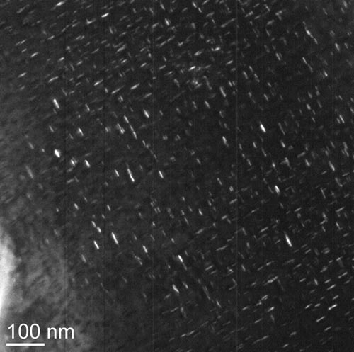
Figure5: TEM dark field image of γ'' precipitates (bright lines).
High Resolution TEM (HRTEM) imaging in Fig. 6 is used to detect coherency, strain fields on the interface between matrix and precipitate and crystal defects.
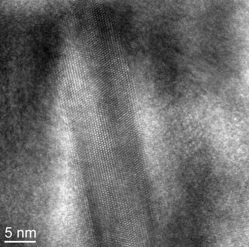
Figure6: HRTEM image of a semi-coherent γ'' precipitate.
Rolling and extrusion of Al changes completely the microstructure of the material. The microstructure has a strong impact on the macroscopical properties of the final product. Deformation, recrystallization and recovery are the main processes occurring during and after rolling. With Electron Backscatter Diffraction (EBSD) we can measure grain sizes, aspect ratios of grains, textures, crystallographic orientations of single grains and recrystallized fractions over areas up to several square millimeters. In the particular case, an inverse pole figure of a rolled Al alloy is shown in the figure below. Elongated grains with different crystallographic orientations (colors) are visible. The arrangement of the elongated grains results in a rolling texture. Further quantitative analysis gives values for mean grain size, aspect ratio, texture, recrystallized fraction and more.
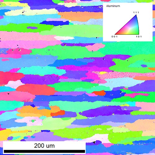
Inverse pole figure of a rolled Al-alloy obtained by EBSD. Different colors indicate different crystallographic orientations of the grains.
Phase stabilities
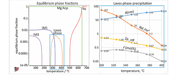
We can evaluate temperature-dependent phase stabilities in a wide alloying range: for instance, dissolution temperatures of gamma´ strengthening phase, calculated for more than 40 different technological Ni-base superalloys with our thermodynamic nickel database ME-Ni are in excellent agreement with experimental data. We predict the thermal stability limit of gamma’ phase with a mean deviation of 22°C
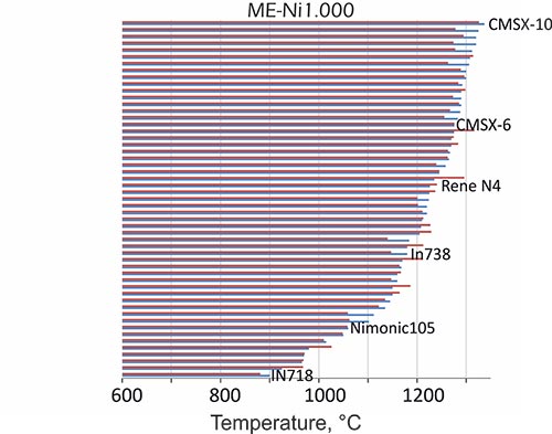
Figure1: Dissolution temperatures of γ’, calculated (red bars) for various technological Ni-base superalloys, compared with experiments (blue bars).
Relevant stable and metastable precipitate phases can be identified by thermodynamic calculations of phase fractions, employing thermodynamic Matcalc Engineering databases.

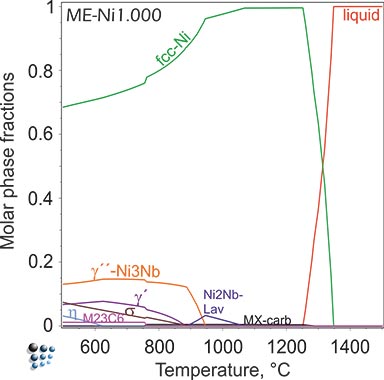
Figure2: Equilibrium calculation of phase fractions versus temperature in Ni-base superalloy IN718 (top). Metastable calculation, suspending thermodynamically stable δ-Ni3Nb phase (bottom) This calculation reveals the metastable stability of technologically relevant strengthening phase γ''-Ni3Nb.
Steels and Hydrogen embrittlement
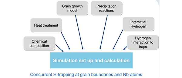
The development of steel, which is resistant against hydrogen embrittlement, is a major research focus and highly challenging since typical operation temperatures range from -150°C to 600°C.
H embrittlement can occur during manufacturing, welding or from services in an aqueous, corrosive or gaseous environment that charge H into the steel. Depending on the prevalent mechanism, several influencing factors must be considered, such as the varying hydrogen diffusivity as a function of the number and strength of traps, the yield stress of the material, the fracture toughness and the hydrogen potential at the sample surface.

Different types of hydrogen traps
Our solution: A quantitative calculation of hydrogen redistribution would allow deeper understanding of hydrogen embrittlement in the materials and open the possibility of prediction and prevention of this type of material degradation.
By application of MatCalc it is possible to understand and analyze the evolution of the microstructure during processing and application. This, in combination with the cell simulation method gives us the opportunity to analyze the diffusion of H-atoms through the material and their trapping respectively. As a result, it is possible to optimize the production route, heat treatments and the alloying concept of the steels.
Typical applications
H-charging and –discharging behavior of different steels in the presence of traps, prediction of the optimal cooling rates from operating temperatures for maintenance to prevent H induced damage, parameter studies on the influence of trapping energies between H atoms and precipitate interfaces on the H-diffusion, evaluation of the relation between size and shape of precipitates and trapping capacity

Sketch of the simulation grid for the calculated hydrogen charging and discharging process


Parameter study: Case 1 – Influence of the trapping energy Case 2 – Influence of a variation in the trap density
Example for vessel maintenance
Material: C-2.25%Cr-1%Mo – Mo2C as active traps
Vessel in operation at 400°C, traps are filled during operation
Discharging from operating temperature to room temperature for technical service is simulated at different cooling rates until ![]()

Free H content after cooling at different cooling rates (CR)

